Industrial supply network
IMB Electric
GIGAVAC Latching high voltage relays — mechanically latched, zero holding current HV relay family in SPST / SPDT / DPDT forms
B2B · PRODUCT SERIES · SENSATA | GIGAVAC
LIVE

Sensata | Gigavac · PRODUCT SERIES

Latching High Voltage Relays — Zero Coil Holding Current

12 models · 8-70 kVdc switching · 10-50 A continuous · Mechanical latch · Zero coil holding current · SPST-NO / SPDT / DPDT cross-forms

The GIGAVAC Latching family mechanically latches the contact in either position and requires no continuous coil current. A single coil pulse toggles position permanently; the contact stays put even when control power is lost — ideal for satellites, portable test gear, battery-powered systems and continuously-energised protection circuits.
Frame-dependent contact configurations span SPST-NO (Form A), SPDT (Form C) and DPDT (2 Form C); each model card explicitly states its contact form and cross-links to the equivalent non-latching variant. Switching range covers 8 kVdc up to 70 kVdc with 10 A to 50 A continuous current.
Zero holding current makes thermal load and energy consumption negligible in battery / ESS load disconnect, satellite isolation and remote-controlled HV transfer applications. The configurator generates the original Sensata part-no automatically based on contact / coil / mount selections.

Satellite & Space SystemsBattery / ESS Load DisconnectPortable HV Test EquipmentRemote HV TransferContinuously-Energised ProtectionATE & Automatic TestScientific InstrumentationLow-Power / Battery-Powered Systems
SERIES CERTIFICATIONS09APPROVALS
  • UL1604
  • IP67
  • IP69K
  • SAE J1171
  • ISO8846
  • RoHS
  • cRUus
  • CE
  • EPIC®

Certifications vary by model — see the corresponding model datasheet for details.

REFERENCE SPECIMENLATCHING · 01
GIGAVAC Latching high voltage relays — mechanically latched, zero holding current HV relay family in SPST / SPDT / DPDT forms
HERMETIC · LATCHINGLATCHING HV RELAYSENSATA
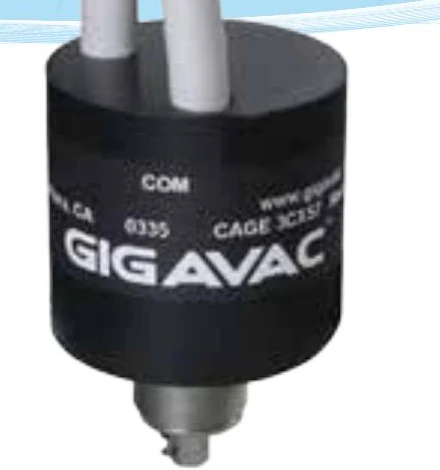
Latching Relays series family image; this model's body and terminations may differ.
Models
12
Products
129
01Max. Switching Voltage
70 kVdc
02Max. Continuous Current
50 A
03Holding Current
0 A · Mechanical latch
04Model Count
12 models
02

Latching Models

12 models · Holds state without continuous coil power

12 MODELS6 PRODUCTS
CONFIGURATORMODELContact FormContact Voltage (kV)Continuous Current (A)Mounting TypesPDF
G12L
Form C, DPDT8kV10—Datasheet (PDF) — G12L
G13L
Form C, DPDT15kV10—Datasheet (PDF) — G13L
G15L
Form C15kV12—Datasheet (PDF) — G15L
G2L
Form C15kV50—Datasheet (PDF) — G2L
G8L
Form C15kV30—Datasheet (PDF) — G8L
G62LC
Form C25kV18—Datasheet (PDF) — G62LC
G60L
Form C35kV12—Datasheet (PDF) — G60L
G61LA
Form A35kV10—Datasheet (PDF) — G61LA
G61LC
Form C35kV10—Datasheet (PDF) — G61LC
G64LC
Form C50kV10—Datasheet (PDF) — G64LC
G71LA
Form A70kV10—Datasheet (PDF) — G71LA
G71LC
Form C70kV10—Datasheet (PDF) — G71LC
MODEL CONFIGURATOR · LATCHING
LIVE

STEP-BY-STEP CONFIGURATION

Haven't picked a model from the table? Configure from scratch

Pick token by token following the manufacturer's coding table; we'll generate the exact part number and open a tailored datasheet.

BELOW · LIVE PREVIEW

TECHNICAL DIFFERENTIATORS

Why Latching Series?

Position-Retained Behaviour

  • Position retained on coil loss

    Natural fit for the 'preserve current state' safety philosophy — storage, standby, long-term isolation.

  • Power-cycle resilience

    Position does not change during system reset / maintenance — no reconfiguration needed.

Three Contact Forms Under One Family

  • SPST-NO · SPDT · DPDT latching

    Form A (G61LA, G71LA), Form C SPDT (G15L, G2L, G8L, G62LC, G60L, G61LC, G64LC, G71LC) and Form C DPDT (G12L, G13L) under a single header.

  • Parallel cataloguing with non-latching equivalents

    The non-latching equivalent on the same chassis is listed on the corresponding form page — easy to compare and switch.

Wide HV Range

  • 8 kV — 70 kV voltage range

    Industrial HV (G12L, G13L) and ultra-high voltage (G71LA, G71LC) under the same latching philosophy.

  • 10 — 50 A continuous current

    Single family from signal/measurement level to mid-power switching.

Driver Design and Thermal

  • Low-power pulse driver is enough

    No continuously-current coil driver required; simple pulse circuitry and low thermal loss.

  • Datasheet pulse timing must be respected

    Wrong polarity or insufficient pulse width corrupts position change — the timing diagram is critical.

Zero-Hold-Current Magnetic Latch

  • Pulse-driven open / close, 0 W consumption afterwards

    The coil draws energy only at the moment of switching — no energy in long-term stable position.

  • Ideal for battery-backed systems

    Dramatically extends battery life in low-power-budget portable / off-grid HV equipment.

DATASHEET · GUIDE · APPLICATION NOTE

Latching Series — Technical Resources

Datasheets

  • GIGAVAC Latching Form A — G61LA, G71LASOON
  • GIGAVAC Latching Form C SPDT — G15L, G2L, G8L, G62LC, G60L, G61LC, G64LC, G71LCSOON
  • GIGAVAC Latching Form C DPDT — G12L, G13LSOON

Selection Guides

  • Latching vs Monostable — Decision FlowSOON
  • GIGAVAC Latching Family Selection Guide — Form A / Form C SPDT / Form C DPDTSOON

Application Notes

  • Pulse Driver Circuit Design and TimingSOON
  • Latching Positioning in Battery-Backed HV DisconnectsSOON
  • Power Budget in Off-grid and Portable HV Test EquipmentSOON

FREQUENTLY ASKED QUESTIONS

About the Latching series

RELATED INSIGHTS · LATCHING
LIVE

RELATED INSIGHTS

Go deeper

01 ENTRIES

// end of index · 01 / 01